|
|
|

| HOME |
It is very important to understand some basic types of coordinate systems used in Noobeed. They are:
- Pixel
coordinate system (Matrix object)
- image
rectangular coordinate system (Image object)
- Photo
coordinate system (Photo object)
- Model
coordinate system (Model object)
- Ground
control coordinate system
- Linear
array coordinate system (SPOT object)
- Space
rectangle coordinate system and Topocentric coordinate system (see Geodesy and Surveying example).
Pixel coordinate system (Matrix object)
Pixel coordinate system is for a Matrix object. A digital image is essentially a Matrix, consisting of a certain number of rows and a certain number of columns. A row has its orientation in a vertical direction, while a column is in a horizontal direction. The first row is always at the top, and named row number 0. The first column is at the left most, and is call column number 0. A matrix index consists of two integers, representing a row and a column number. The first number is for a row number and the second is for a column number. For example an index (5, 9) means at row number 5 and column number 9. Please be aware that row number 5 is actually the 6th row from the top and column number 9 is the 10th column from the left. Below is a figure to depict the matrix index system.
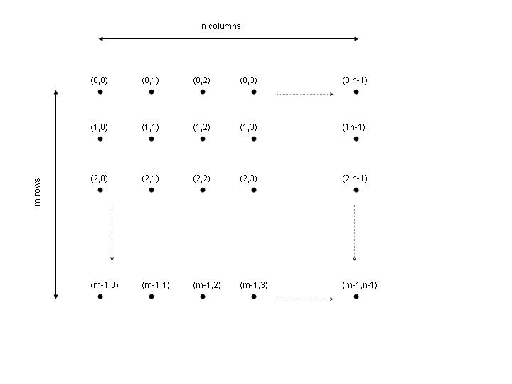
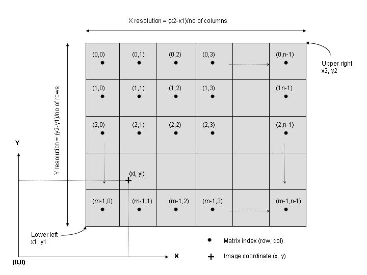
Image rectangular coordinate system (Image object)
Rectangular coordinate system is for an Image object. An Image object is essentially a Matrix object with known coordinate of the lower left and upper right corners. Unlike matrix index system, or pixel coordinate system, which has no real physical dimension, image rectangular coordinate system is a finite coordinate system, having a real world distance unit, e.g. meter, feet etc. The rectangular coordinate system is a right hand system, in which horizontal axis is call x-axis and vertical axis is called y-axis.
An image object in Noobeed is actually a matrix, which known coordinates of two corner points, lower left point and upper right point. While each element in a matrix is theoretically area-less, occupying no spatial space, an Image object has an extent over a spatial area, and this is the main difference between a matrix and an image. To pinpoint at a particular location in an image, we use a rectangular coordinate, x and y. This is just an ordinary right hand coordinate system, with the X-axis as a horizontal line and the Y-axis perpendicular to the X-axis. The origin of the system can be at anywhere in space, inside or outside the image.
By giving
the coordinates of the lower left and upper right corner of an image, its
spatial orientation as well as it spatial scale are definitely defined.
It is worthwhile to notice that rows in a matrix are parallel to the X-axis,
and columns are parallel to Y-axis. The positive direction of X-axis is
the same as that of column number. However the positive direction of row
number is opposite to that of the Y-axis.
By definition, each pixel is an image will cover a certain amount of area, in which any points lies within the area will share the same attribute value, the value of the matrix element fall within that pixel. The width of a pixel in X-direction and in Y-direction may be different. They are called x resolution and y resolution.
Apart from
being a finite coordinate system, the image coordinate system has a major
advantage over pixel coordinate system because it can
preserve the positional information of an extracting image correctly. One example is, suppose we want to cut a
portion of an image, say B, from an
original image, say A, then we can use the WINDOW class fuction, like B =
A.WINDOE(x1, y1, x2, y2). The resulting image B will carry all the positional
information with it correctly.
Therefore, all pixels in the B image will have exactly the same x y
coordinate as those in the original image A.
However, this will not be the case with the Matrix object, i.e. if the
cut a portion of Matrix out of another Matrix, the new Matrix will have it own
pixel coordinate system, therefore, pixels of the same features but in
different images will have different pixel coordinates.
Below is a figure to depict the image rectangular coordinate system.
Functions used to convert between matrix index system and image rectangular coordinate system back and forth are, for examples, xy2rc, rc2xy, x2col, r2row.
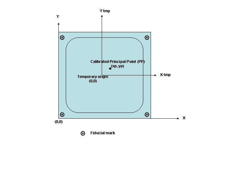
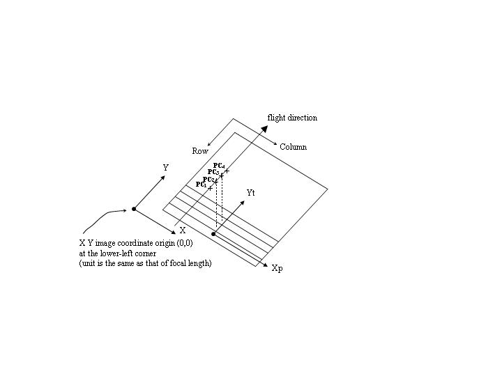
Photo coordinate system (Photo object)
Photo coordinate system is for a Photo object. Photo coordinate system ultimately wants its origin at the so-called "calibrated principal point".
To explain the whole story in details would not be appropriate here. Users who are not familiar with photogrammetery should consult reference books. In practice, there is a sort of temporary coordinate system that a camera calibration report used to define the principal point. This is called a fiducial mark coordinate system. It does not matter that how this system is set up. The most important information that a photogrammetric camera needs to have is the coordinates of fiducial marks. Those coordinates are given in the camera documentation file, of a camera object. Usually the origin of the temporary system, fiducial mark system, is very close to the principal point. The shift of the principal point from the fiducial origin is described as a coordinate, xp and yp, which must be given in the camera file. The concept is depicted by the following figure.
By observing position of those fiducial marks in a matrix index system, rows and columns, and the given coordinates of them together with the values of xp and yp, we are able to calculate a set of parameters, which allowed us to transform back and forth between photo coordinates system and matrix index system. This process is called Interior Orientation (IO).
As a matter of fact, Noobeed does not directly relates photo coodinate system with pixel coordinate system. It determines transformation parameters to transform back and fort between image rectangular coordinate system and photo coordinate system. The transformation between image rectangular coordinate and pixel coordinate is done via functions of an image object.
Functions in Noobeed used to convert between matrix index system and photo coordinate system back and forth are, for examples, xpyp2rc, rc2xpyp.
In modern digital camera, there is no fiducial mark and therefore no need for observation for IO. The user simply call a special IO function called IO_digital, then the relation between photo coordinate and fiducial coordinate is established. Here the fiducial coordinate system is originated at the center of the image and the four corner of the image is regarded as fiducial marks in the old classical analog camera sense. To do this, we must specify the size of each pixel, both in x and y direction, then by using the size or the number of rows and columns of the image, the coordinates of the four corners of an image cen be determined, referencing to the center of the image which has the coordinate value of (0, 0). The size of image pixel is input via the camera file in the fiducial mark coordinate list. See class function IO_digital of the Photo class for details.
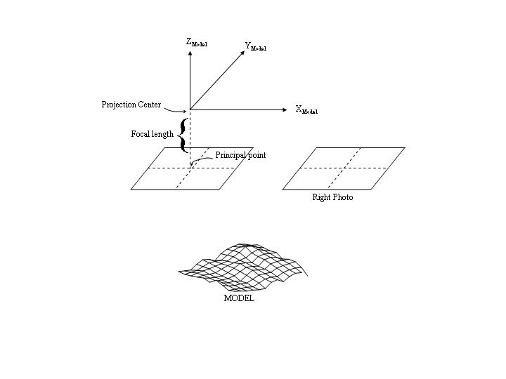
Model coordinate system (Model object)
Model coordinate system is for a Model object. Unlike image or photo coordinate system, Model coordinate system is three-dimensional. It is a temporary coordinate system that classical photogrammetry utilizes to describe position of points in a stereo-model. A model is so-called reconstruction when all light rays projected from the left photo intersect with all correspondent light rays from the right. It can be achieved by performing Relative Orientation (RO).
Depending on definition, model coordinate systems can be different from one to another. Noobeed sets the model coordinate system at the Projection Center (PC) of the left photo. Its z-axis points upwardly and perpendiculars to the photo plane. The x-axis of the model coordinate system is parallel to x-axis of the left photo coordinate system. It should be noted that all z model coordinates are negative. The unit of model coordinate system is kept equal to that of photo coordinate system, for example milimeter.
Ground control coordinate system
Ground control coordinate system in general is that of map projection coordinates together with elevation above a certain datum, e.g. mean sea level. This loosely defined definition sometimes can cause problems since the z-axis, elevations, is not always perpendicular to the x y plane, for example when the area coverage is very large and the earth curvature can not be neglected. Noobeed regards ground control coordinate system as a general rigid 3D right hand coordinate system, where all three axes are perpendicular to each others. For serius uses who want to accurately determine a real world position of a point on images, one solution is to emply a tempolary 3D local cartesian system where all ground points are transformed to their geographic coordinates before tranforming to the 3D local system.
Linear array coordinate systems (SPOT object)
Unlike a traditional aerial photo, which is basically a single shot frame-image, a SPOT satellite image, for example, is an image consisting of a number of shot of a linear array strung together to form a frame-look-like image.
Strictly speaking, each row of the image acts like an individual photo in conventional photogrammetry, with its own projection center and orientation parameters. Hence y coordinates at the center of pixels are always zero, and X coordinates is at the center of the array, however shift by the principal point coordinate, if exist.
1. row and column matrix index
This is exactly the same as that of matrix, i.e. (4, 67) means row number 4 and column number 67. The first pixel has an index of (0, 0) at the upper left of the image.
2. image rectangular coordinate system
image rectangular coordinate system the same as that of Image object is utilized here. This is a right-hand coordinate system, origin at the lower-left corner of the image. The unit is the physical unit described by the length of the array, for example 78 millimeters for SPOT. Hence the upper-right corner of the image will have a coordinate (78.0, 78.0), if the image has the same number of rows and columns.
3. photo / time coordinate system
The term "xpyt" is used here as x photo coordinate and t (time).
While xp is x-photo coordinate in the same sense as that of frame aerial photo, yt, or time, indicates which particular set of EO parameters be used.
Essentially there are as many as no-of-row sets of EO parameters, e.g. 6000 sets of EOPs for 6000 rows.This system is made by shifting the x origin of the image system to the center of the array, and converts the y coordinate to time. A y coordinate is converted to pixel unit and multiply by the scan time per row. For example scan time for SPOT is 9 second for 6000 rows, thus scan time per row is 0.0015 seconds.
| HOME |